Household Water System
I put together the description below as part of the article on fault tolerance of the house, but then decided to also
factor it out into a separate post.
One of the realities of living in rural area is having to maintain one's own well. On one hand, this means
not having to pay for water - but on the other hand, if any of the complex machinery of your water system
breaks - it is extremely unpleasant.
To understand what can break, we should first understand how water system works.
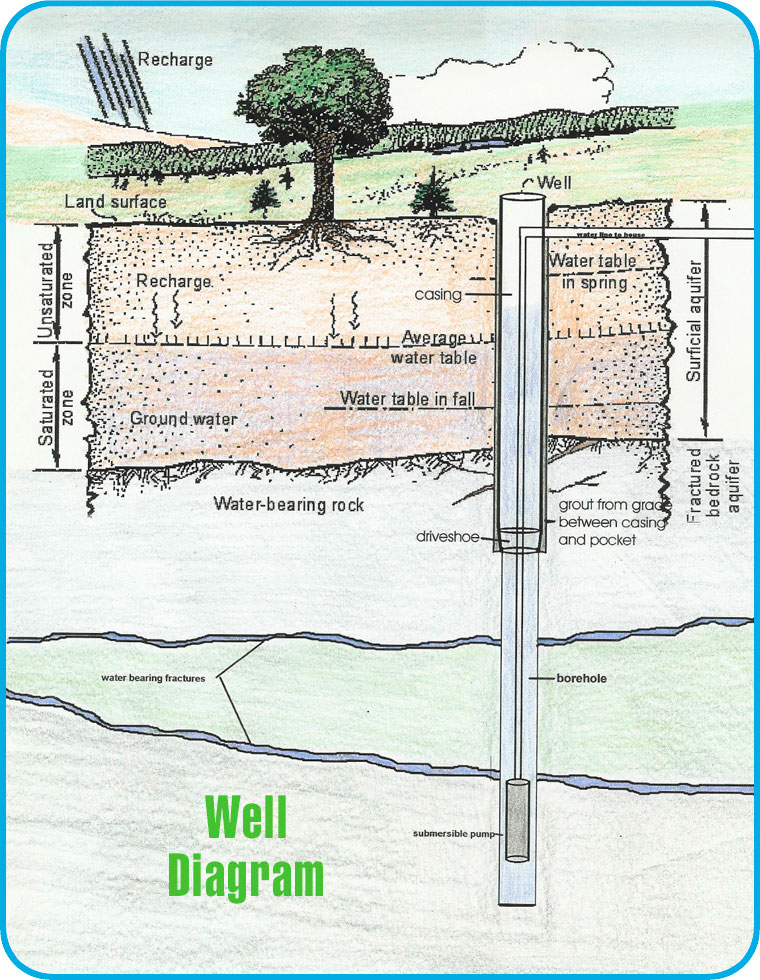
A typical water system consists of a vertical shaft that goes into the ground, encased in steel pipe.
The depth of it, depending on the water table, can be anywhere from 50ft to 250ft.
Into that hole the pump is lowered on a pipe, usually 1-2" diameter, which is made of 20ft
individual segments. This is used to both support the pump and also pipe the water to the
surface.
The pipe hangs on a special adapter that is welded to the side of the casing which sits below the frost line.
On the other side of the casing it is connected to the water main.
The water main leads to the house where - usually - a pressure tank would be installed. Buried right by the
water main there is the electric cable that feeds the pipe. That goes to the pump controller.
While usually the pressure tank and the pipe controller are in the house, this does not have to be the case.
On my property there is a well house where all this equipment is housed, and there is another well which
has the pressure tank and the pump controler in an underground structure located right by the pump.
The function of pressure tank is to maintain the water pressure in the house without the pump running.
Pumps used in modern wells are very, very powerful. It makes no sense to turn them on every time one
needs a cup of water. Instead, there is a reservoir of water - 10-50 gallons, depending on the
pressure tank size - which is kept under pressure by the bubble of air at the top of the tank.
When the tap is open, the air expands and pushes the water out of the tank and into the tap. When
the tank is near exhausted, the pressure-activated switch turns the pump back on and refills the tank
(thus compressing the air inside it and creating durable pressure in the system).
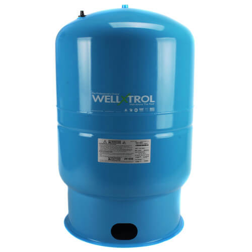
This is a pressure tank.
The two electrical components that every well has is a pressure switch and a pump controller. The pressure switch
is almost always mounted right by pressure tank. It turns the system on when the pressure drops below certain level,
and turns it back on when it reaches certain level. These levels are usually 30psi and 50psi.
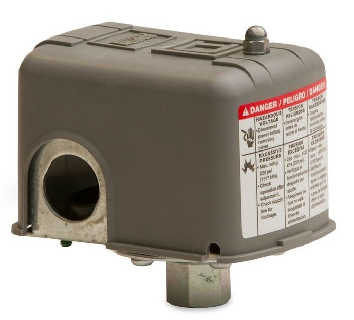
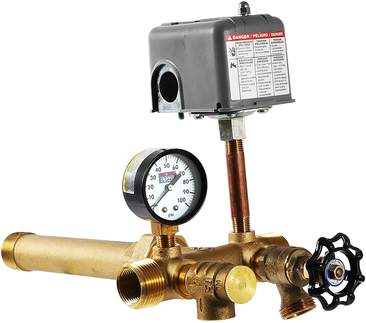
This is a typical pressure switch. And this is how it is typically installed:
The pump itself is driven by something called a "pump controller". Control box has a couple of capacitors and relays
that ensure that during startup - when the power demand of an electric motor peaks - the pump has enough power.
It basically charges the capacitor, and when capacitor gets enough charge, flushes that charge into the motor.
Pump control box is always matched with the pump - the voltage and wattage (or horsepowerage :-)) are extremely
important. So when buying a new control box ALWAYS know what pump you have (or just buy the exact same version as
you already have).
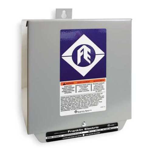
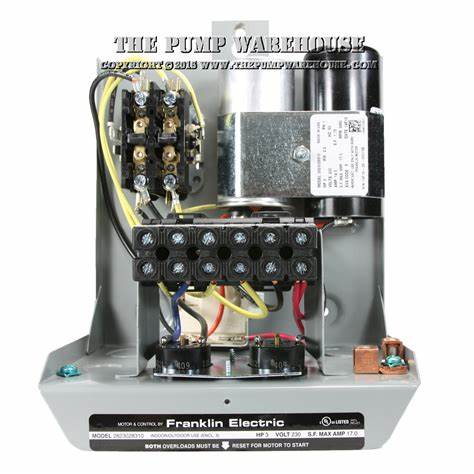
This is a pump control box. Capacitors are the cylinders on the top right.
The control box shown above is a "deluxe" version of the control box. Regular control box is connected to the
pressure switch in series. When the pressure switch triggers, it powers the control box, which after a tiny period
of time (when capacitors charge) starts powering the pump. When the pump is shut off, the control box is not powered.
The "deluxe" version of the control box has the power wired to it, and then it has the separate wire pair that go
to the pressure switch. When the pressure switch triggers, the relays in control box connect the power to the pump.
Control boxes have some primitive protections about overloads - if pump stalles and the current through it exceeds
some value, they will disconnect. There is a tiny button (or two, depending on the design) at the bottom of the
control box that allows resetting it.
Sometimes you will see another box wired into the pump circuit called "pump saver". It will look like this.
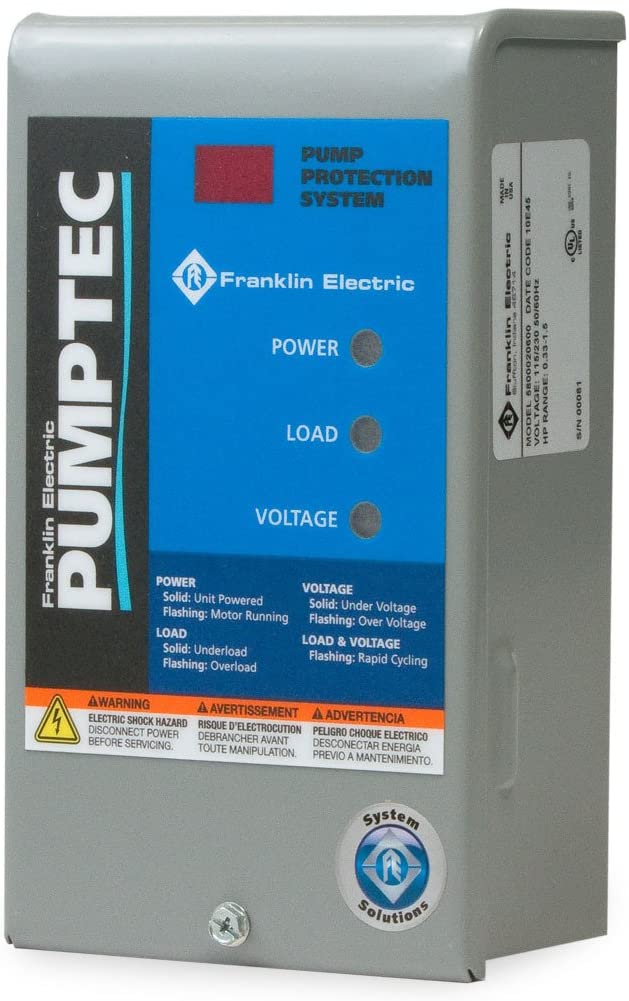
Pump saver contains a computer that analyzes the current going through the pump. The current fluctuates a little
depending on how pump rotates. When the water in the well runs low, the pump will rotate faster than usual, and
if the pressure in the system is too high, the pump will rotate faster than usual. The computer inside the pump saver
senses this, and cuts the power to the pump.